Week 14: Interface and Application Programming
What should I do this week?
In this fourteenth week of Fab Academy, there are two types of assigments. The individual assigment is to write an application that interfaces with an input &/or output device that you made.
The group assigment is to compare as many tool options as possible. Further learnings are listed below:
- Explain the UI that you made and how you did it.
- Include original code that you have used
- Explained the programming process used
- Explain the mistakes that I had made and how I corrected it
- Include hero shots of the board
- Link to the group assignment page
- Include the design files used
- Try out a cool experiments
The following are the softwares that I have used for learning various operations:
- Arduino IDE : Programming
- Processing 3 : User Interface
- MIT App Inventor : User Interface
The main goal of this weeks assigment is write an application that can interface with the input and output device that I had created. For this weeks assigment, since the lab is closed due to the pandemic, I plan to try out both MIT App Inventor and Processing 3 and try out coding using the latter. I will try to document all that I had learned and will test out the learnings once I have access to the lab.
Week 14: Action Plan
| |
|
|---|---|
| Wednesday | Prof. Neil's class on Interfacing and Application Programming |
| Thursday | Researching about programming languages |
| Friday | Getting to know about Processing 3/ MIT App Inventor |
| Saturday | Documentation |
| Sunday | Documentation |
| Monday | Programming |
| Tuesday | Documentation |
Interfacing with Processing 3
Processing is a flexible software sketchbook and a language for learning how to code within the context of the visual arts. Since 2001, Processing has promoted software literacy within the visual arts and visual literacy within technology. There are tens of thousands of students, artists, designers, researchers, and hobbyists who use Processing for learning and prototyping. The advantages of Processing is listed below:
- Free to download and open source
- Interactive programs with 2D, 3D, PDF, or SVG output
- OpenGL integration for accelerated 2D and 3D
- For GNU/Linux, Mac OS X, Windows, Android, and ARM
- Over 100 libraries extend the core software
- Well documented, with many books available
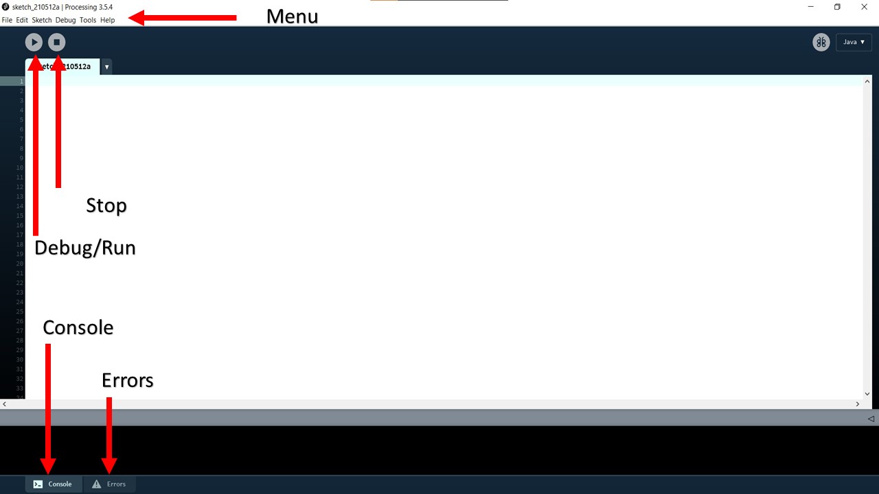
The interesting part is that the user interface of the Processing 3 is very much similar to Arduino which makes it easy for us to learn and program. This image will introduce you to the various tools available in Processing 3 software.
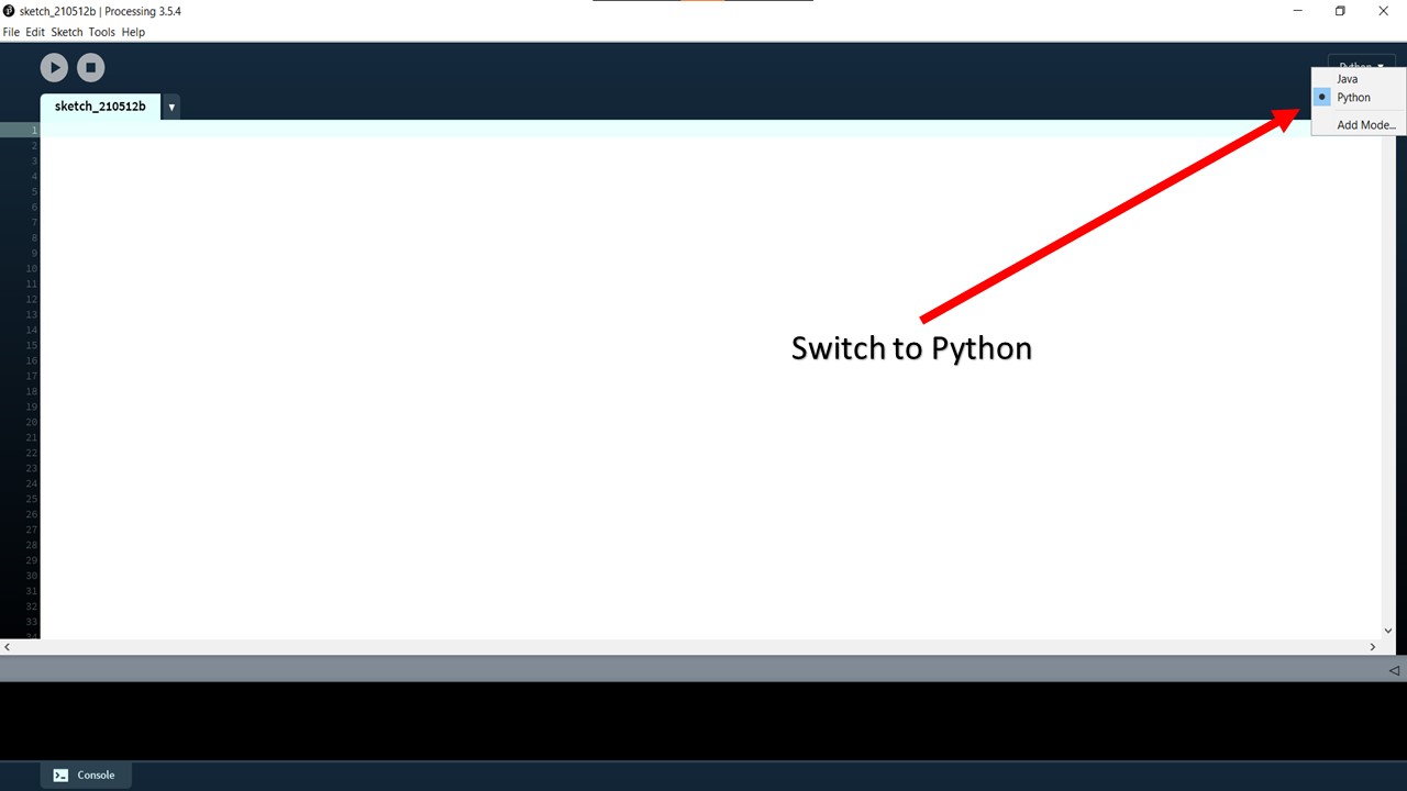
The structures in arduino and processing are almost similar. "void setup" serves a similar role of arduino "void setup" and also the "void draw" in processing is also doing a similar functionality of "void loop" in arduino. We also has the freedom to choose between Java, Python, R etc. for coding in Processing 3. If you want to code in Python you need to select Python from drop down menu located in top right hand corner of the interface.
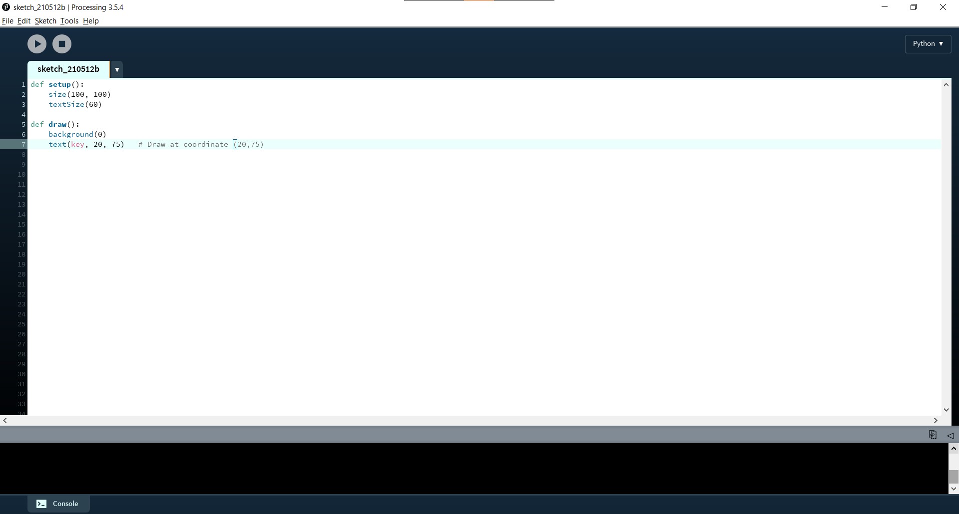
Now I am going to try out some programs to test out my coding skills. For this I am referring Processing Interactivity Tutorials. published by MIT Press. I am planning to write a Python program that would show the key that I had pressed using Keyboard as the output. The logic behind the program is that: Processing registers the most recently pressed key and whether a key is currently pressed. The boolean variable keyPressed is true if a key is pressed and is false if not. Include this variable in the test of an if structure to allow lines of code to run only if a key is pressed. The keyPressed variable remains true while the key is held down and becomes false only when the key is released. The key variable stores a single alphanumeric character. Specifically, it holds the most recently pressed key. The key can be displayed on screen with the text() function. For the program, I had first specified the textsize and gave a black background. Now the key that I press will be shown in the given coordinate. The program is shown below:
In the below figure, when I press letter A in keyboard the letter will be shown in black background. This gives a basic idea about how easy the Processing 3 is to program.

I didn't try to program for input/output device as I didn't have made the board till now so I will program once I fabricate the board.
Interfacing with MIT App Inventor
App Invetor is an Open-source, Cloud based Web application that t allows newcomers to computer programming to create software applications for the Android. It uses a graphical interface, very similar to Scratch which allows users to drag-and-drop visual objects to create an application that can run on Android devices. After a couple of tutorials, you will be able to create a wide variety of apps. The UI is straight forward.

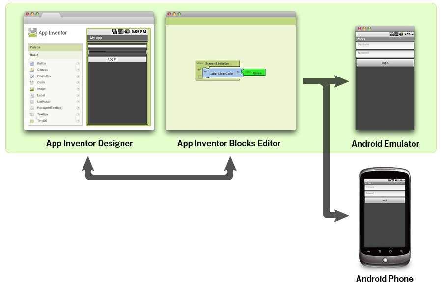
There is no coding, but you program visually by dragging and dropping logic blocks like 'If else'. The App Inventor has 2 parts: The App Inventor Designer, where you select the components for your app & The App Inventor Blocks Editor, where you assemble program blocks that specify how the components should behave. Your app appears on the phone step-by-step as you add pieces to it, so you can test your work as you build. When you're done, you can package your app and produce a stand-alone application to install.
The App Inventor development environment is supported for Mac OS X, GNU/Linux, and Windows operating systems, and several popular Android phone models. Applications created with App Inventor can be installed on any Android phone. For this interfacing, I am planning to control the LED light using the phone through an application build using MIT App Inventor.
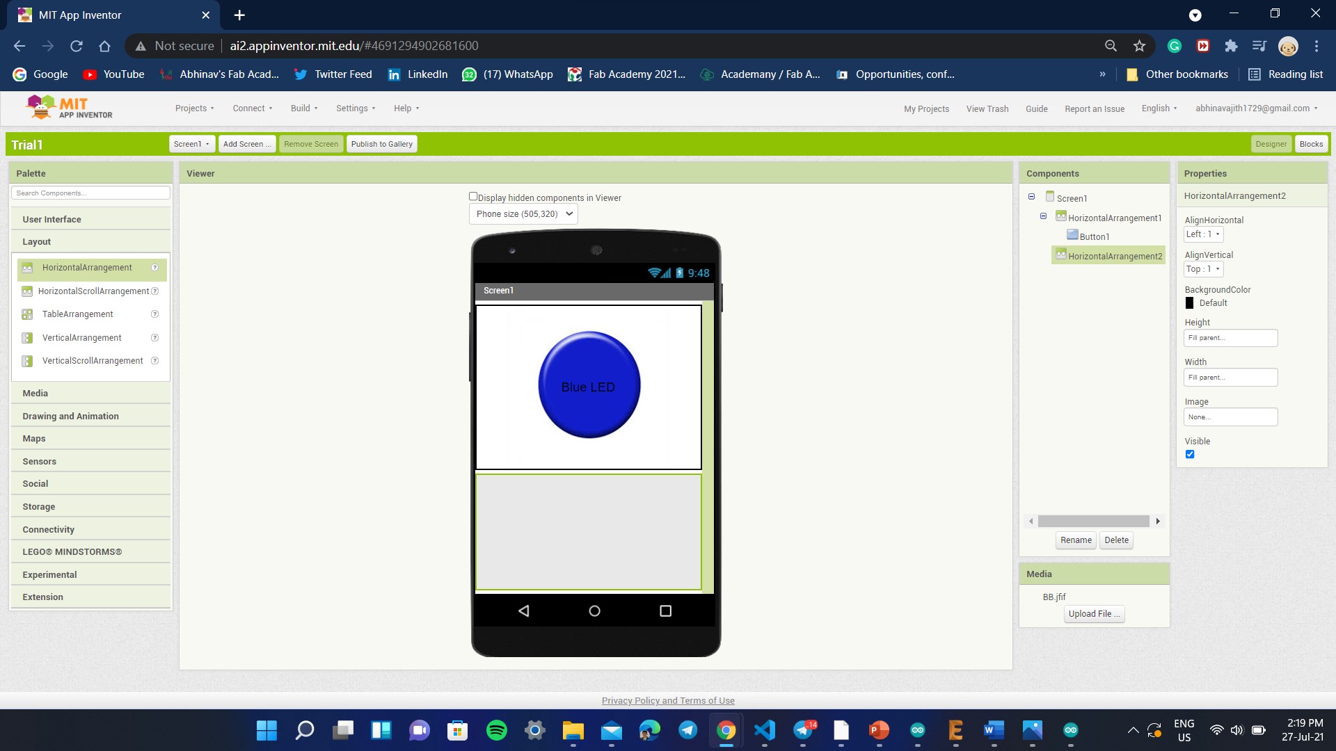
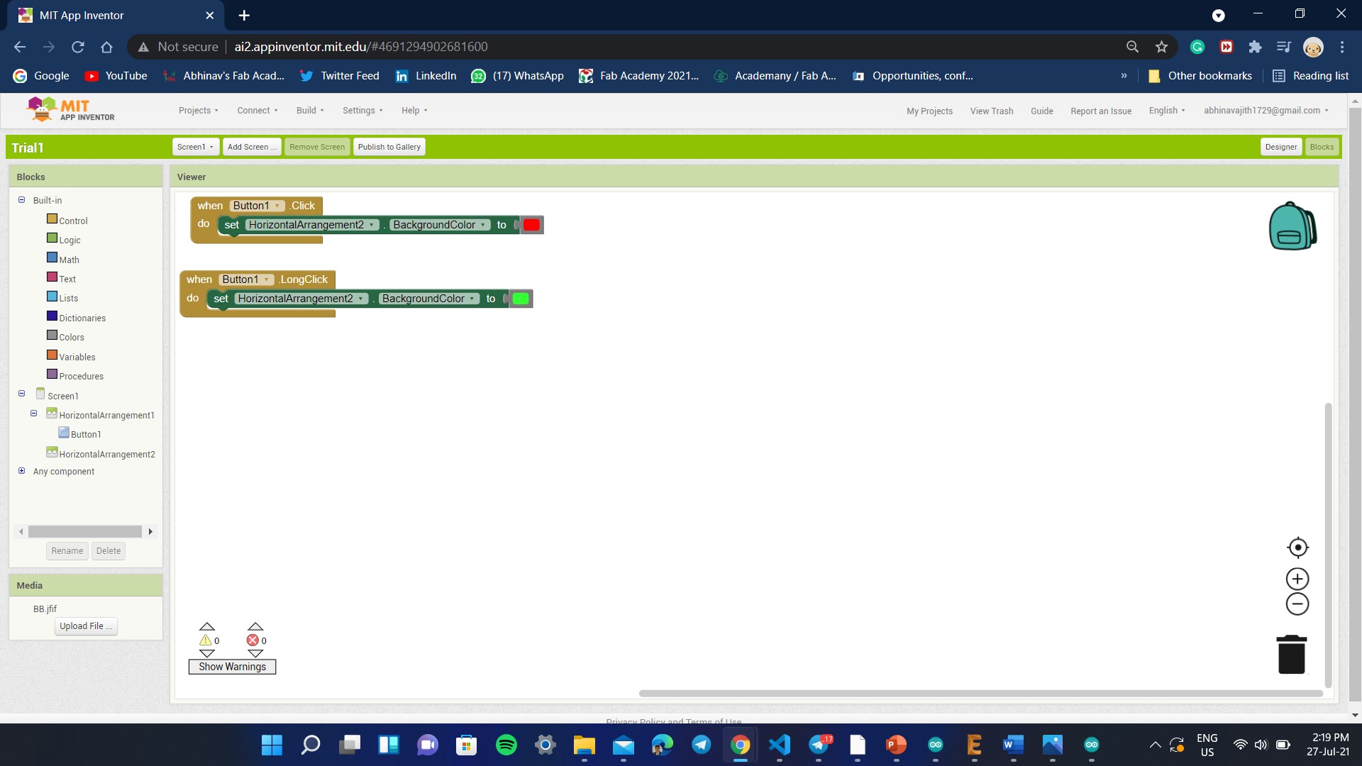
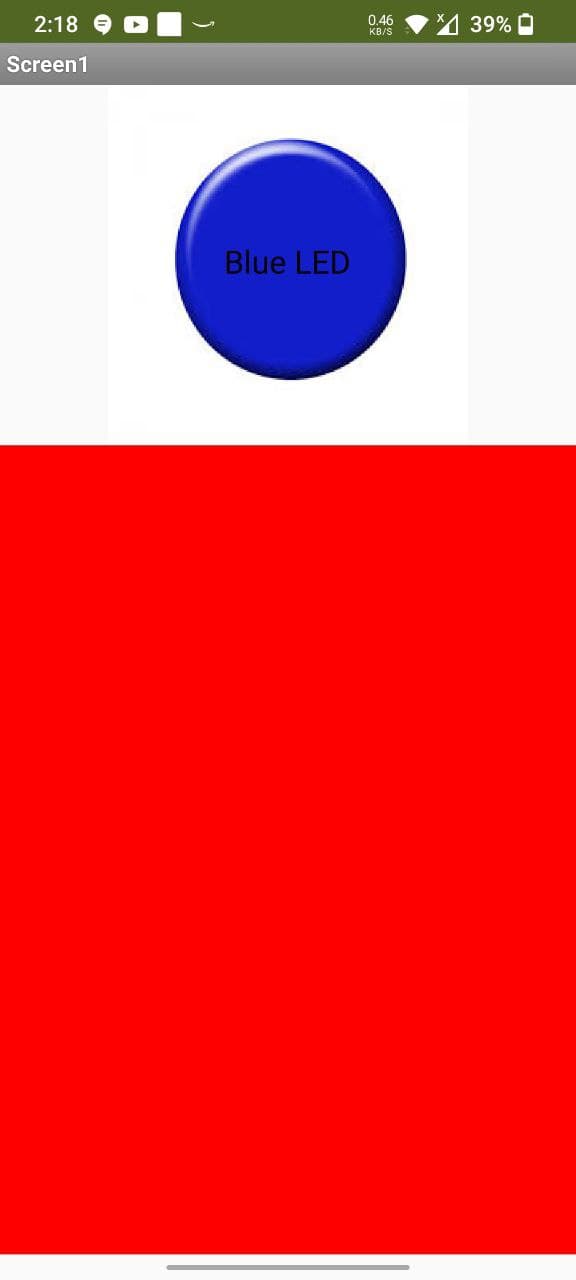
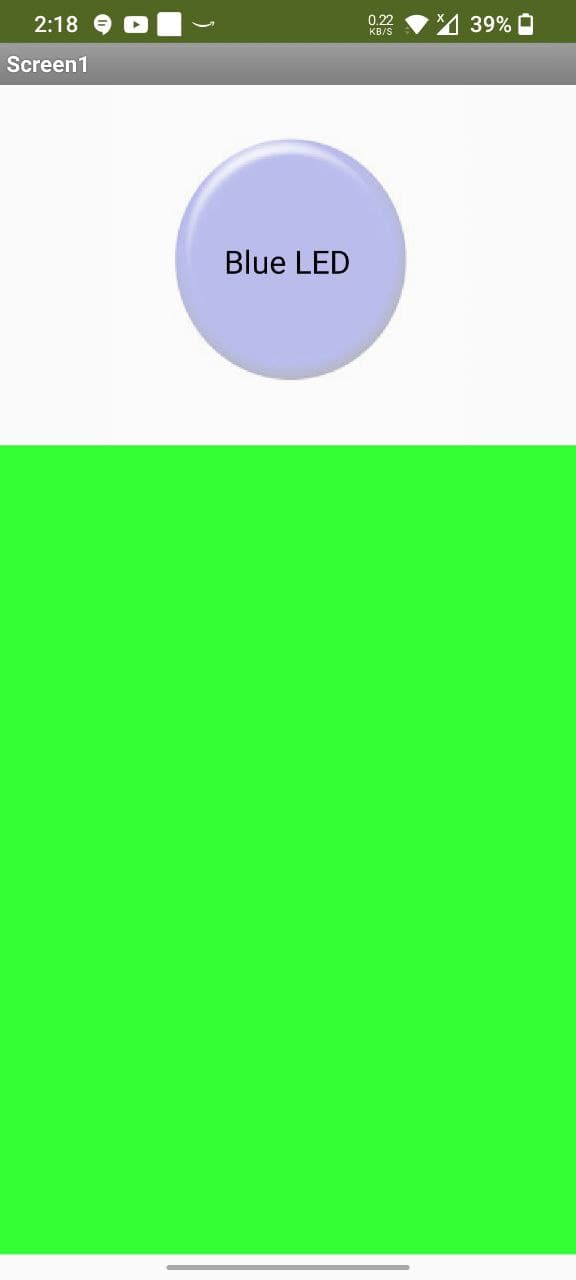
So here, I had tried to make a simple button app, that would change the color of bottom half to red in short press and green on long press. The below image shows the button shape made by importing a primary blue button shape, adjusting height and the next step was to go to blocks and add function. The functions were like little legos and it was quite easy. Then I had launched the MIT AI Companion App in Mobile, scanned QR Code and it worked succesfully.
This app can be further improved to provide more functions. As this was a group assignment done alone by me due to the pandemic, I will add more functions once I find time.
Application Development
The idea of this week's assigment is to make an user interface using Processing 3 and interface it using the custom board that I had made for Input Devices week. The concept is simple, when the user clicks the button with color say blue in the interface, the blue color in the board will turn on. Similary when I click the button once more, the button color will turn to red and the red LED will turn on. The first step to make this happen is by writing the custom code in Processing 3. To start with, I had found the RGB values of red and blue color from the internet inorder to fix the color of the button. The next step was to prepare the size for the window of the interface when opened, after that the background color was also set as per my requirements. I had also incorporated function called "mouseReleased()" to enable to access button when it is clicked. The function (redcol == 0) store the color on one click. The ellipse function was used to decide the shape of the button. The code itself is self explanatory and it is shown below
int redcol = 0; //define value of R
int greencol = 0; //define value of G
int bluecol = 255; //define value of B
boolean button=false;
void setup(){

  size(400,400); //Size of the Window
background(0,0,0); //Black Background

}

void draw(){
   ellipse(200, 200, 150, 150); //Shape of
  fill(redcol, greencol, bluecol);
  stroke(20);
}

void mouseReleased() {
  if ((mouseX>100)&&(mouseX<300)&&(mouseY>100)&&(mouseY<300)&&(redcol == 0)) {
    redcol = 255;
    greencol = 0;
    bluecol = 0;


  } else {
    redcol = 0;
    greencol = 0;
    bluecol = 255;


  }
}
The below image shows the button action when mouse is clicked over it.


The next step is to introduce the serial processing code into Arduino IDE. The following code has been flashed to the custom board
    #include<.SoftwareSerial.h>//Please remove the full stop before the software serial when used
      SoftwareSerial Serial(0,1);

      void setup() {
      pinMode(PA6, OUTPUT); //initializing led1
      pinMode(PA2, OUTPUT); //initializing led2
      Serial.begin(9600);
      }

      void loop() {
        if(Serial.available() > 0) {
        char ledState = Serial.read();
       if (Serial.available() == 0) {
      digitalWrite(PA6, HIGH);
      digitalWrite(PA2, LOW);
       }
       if (Serial.available() == 1) {
      digitalWrite(PA6, LOW);
      digitalWrite(PA2, HIGH);
       }
      }
      }
The code has been tested using serial communication and had worked successfully. The next step is to add the serial communication part to the Processing 3 code. The code is given below:
    import processing.serial.*;
Serial myPort;
int redcol = 0; //define value of R
int greencol = 0; //define value of G
int bluecol = 255; //define value of B
boolean button=false;
void setup(){
  myPort = new Serial(this, "COM10", 9600); //Black background and COM10 Port where Board is connected with baud rate of 9600
  size(400,400); //Size of the Window
background(0,0,0); //Black Background

}

void draw(){
   ellipse(200, 200, 150, 150); //Shape of
  fill(redcol, greencol, bluecol);
  stroke(20);
}

void mouseReleased() {
  if ((mouseX>100)&&(mouseX<300)&&(mouseY>100)&&(mouseY<300)&&(redcol == 0)) {
    redcol = 255;
    greencol = 0;
    bluecol = 0;
    myPort.write('1');

  } else {
    redcol = 0;
    greencol = 0;
    bluecol = 255;
    myPort.write('0');

  }
}
For this week's assignment, since it's concentrated on the interfacing part, I had decided to use my previous custom board to test the program. The board I have has 2 inbuilt LEDs which can be lit based on the on screen button. he program is flashed using FabISP and the real time serial communication is made possible via FTDI cable. The components of the board I had used is given below.

The below video shows the testing part. The code ran successfully and I was very happy to see the results.
Second Try
Here I am using a rectangular button in the interface to control a single blue led. The led turns on when the button in pressed in the interface. The arduino code and processing 3 code is given below
#include<.SoftwareSerial.h>//Please remove the full stop before the software serial when used
SoftwareSerial Serial(0,1);
void setup() {

pinMode(PA2, OUTPUT); //initializing led

Serial.begin(9600);
}
void loop(){
if(Serial.available() > 0) {
char ledState = Serial.read();
if(ledState == 'A'){
 digitalWrite(PA2, HIGH);
}
if(ledState == 'B'){

   digitalWrite(PA2, LOW);
}
}

}
Processing 3 Code
    import processing.serial.*;
    Serial myPort;
    int redcol = 0; //define value of R
    int greencol = 0; //define value of G
    int bluecol = 0; //define value of B
    int blackcol = 0;


    boolean button=false;


    void setup() {
      myPort = new Serial(this, "COM10", 9600);
      size(300, 300);

    }


    void draw() {

      rect(100, 100, 100, 100);
       fill(redcol, greencol, bluecol);
      stroke(10);
    }

    void mouseReleased() {
      if ((mouseX>100)&&(mouseX<300)&&(mouseY>100)&&(mouseY<300)) {
        if (bluecol == 0)
        {
        redcol = 0;
        greencol = 0;
        bluecol = 255;

        myPort.write('A');
      }
    else
      {
        redcol = 0;
        greencol = 0;
        bluecol = 0;
        myPort.write('B');
      }
    }
    }